
Wire harness development and testing
Wire harness development and testing
Slow is painful
by Jon M Quigley
Vehicle Systems
Vehicles have become increasingly electrical over the year, even vehicles that are not electric propulsion. There are more features, more embedded controllers and greater communication between the electronic controllers. The range of content is from power electronics, sensor data (analog signals), actuators and switch inputs and outputs, communications (for example, CAN and LIN bus) and many other coordinated electrical signals. For aircraft and commercial vehicle (heavy trucks) the wire harnesses can be quite large with hundreds of interconnection points that extend over great distances. Though the wire harness itself may not be a very complicated component, the mathematics are fairly simple, but creating and integrating the wire harness into the vehicle is a nontrivial task. The complexity of the product is a fraction of the effort, creating the product and evaluation can likewise pose difficulty. Let’s consider the wire harness in the course of developing a new vehicle electrical system.
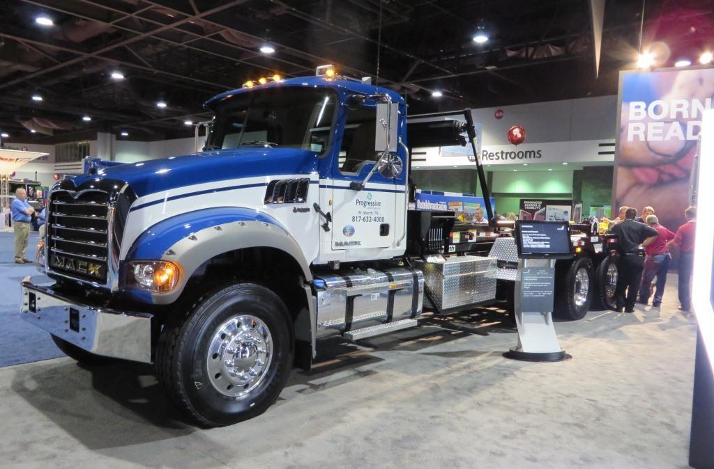
Figure 1 Modern vehicles have large distributed electrical systems.
From experience, the systems engineers apportion the functions of the vehicle across specific systems and electronic control units (ECU). The design is such as to ensure the failures possible are orchestrated in such a way to not inflict great trauma. In future articles we will review these systems engineering approaches. Once the scope of the work is known sufficiently and the system apportionment is defined, work will commence on developing the design. Much of this effort is performed in CAD. Some advanced CAD tools actually provide for simulation of the electrical signals.
Wire harness and interconnections
It is more than just electrical interconnects, but mounting locations, along with the physical structure of the vehicle are considered, and wire routing will need to account for these physicals of the vehicle or vehicles. Armed with this information, we can identify specific connectors and set about routing the wires to individual cavities and around the various surfaces of the vehicle. We will be guided by a few things during this stage of the work one of which is the equation for the wire harness resistance:
Where:
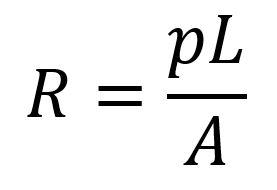
R = resistance of the wire length
ρ = Resistivity (ohm / meter)
L = Length of the wire
A – Cross-sectional area of the wire
We will use this equation to give us the amount of resistance associated with the wire (resistance increases with wire length and decreases with cross sectional area), and vehicle’s that have considerable length, like large trucks and aircraft, can lose signal strength due to long lengths if we do not mitigate this voltage drop by increasing cross sectional area. Increasing cross sectional area adds costs, and makes routing the wires through the vehicle more difficult as the bend radius become much greater with increased cross-sectional area (generally speaking). In fact, the simulations we run will inform us how much loss of signal (or voltage) may be due to the wire harness length and cross-sectional area, along with the current that can be carried, and we can select a larger cross sectional area to reduce the resistance of the circuit and decrease the voltage drop. These things help us determine the wire gauge so that we can carry the current or deliver the voltage to the load and not lose too much signal due the wire length. This will help with the bundling, which wires travel in the same space that can be connecting within one group. Now with the bundling complete, we use the CAD tool to route the harness. These same CAD tools often have simulation capabilities, that will allow the developers to explore how the system works electrically and not just mechanically. All of those individual mechanical models of the subsystem, for example body components such as doors, structural parts, brackets, wire harness and mounting locations, and other physical parts, are put together virtually assembled to allow us to virtually see how the parts fit. In addition, for example, we can simulate load characteristics for wire harness elements to test our assumptions that invariably are baked in the design. These tools may even be sufficiently sophisticated to simulate data bus or serial communications, in these instances we can observe the electrical impact of the wire harness on the digital signals, noting attributes like signal rise time and general shaping as way of confirming the wire harness design will not have a negative impact on the signal shape and strength. Contrary to what many may say, these vehicle projects do not consist of doing all the paper design before the next phase – in decades of experience I have never seen a product developed in the extreme way that many characterize non-agile approaches to product development. The virtual design will be performed via the CAD models (via simulation), possible product incarnations (prototype part exploration).
Product development, Prototypes, Lead time and Learning
Lead times for prototype material can be lengthy and it is wise to find ways to shorten this time where possible. For example, a wire harnesses can be 8-12 weeks for an external entity to build, often from the supplier who will eventually manufacture the production wire harness. This means each design iteration, exploration and opportunity to learn from that part, will take more than 3 months. Product development requires an active learning approach, the faster we learn, the quicker the product can be refined and produced. If our company pays a premium, we may get moved to the front of the queue. We should consider the amount of time that is taken in these design loops for prototype acquisition, and the delays to learning about the product and use this time cost when making the business case for quick prototypes. What is the value (loss of value) of the time spent waiting for parts? Eventually prototype parts will be required to explore how the wire harness system will actually interface with the other systems and fit into the vehicle. This includes learning things about the product such as routing to help with the manufacturing and maintenance of the final vehicle design and any special tools required. Additionally, these prototype parts, coming from the supplier, are opportunities for the supplier to learn also about the future product they will be constructing.
Prototypes there are instantiations of the product built, increasing levels of capabilities and sophistication as the team marches toward the final incarnation of the product. There will be interim builds of the wire harness that will undergo physical exploration, checking for actual fit into the vehicle, and subsequently subjecting the product or subsystem to environmental stresses (such as vibration, and chemical compatibility for example). In addition to these explorations, there will be testing of continuity of the wire harness. These physical explorations tell the customer and the design personnel about the actual part, likewise inform the manufacturing, and eventually these parts will be put into a test buck and a test vehicle that represents the production version of the vehicle as we presently understand. These dimension checks against the drawings along with the continuity testing will have implications on these builds, and are ways of affirming that the product design as documented is equal to the prototype incarnation from the manufacturer. That is, the prototype build does not match the drawing, and one of the two is incorrect.
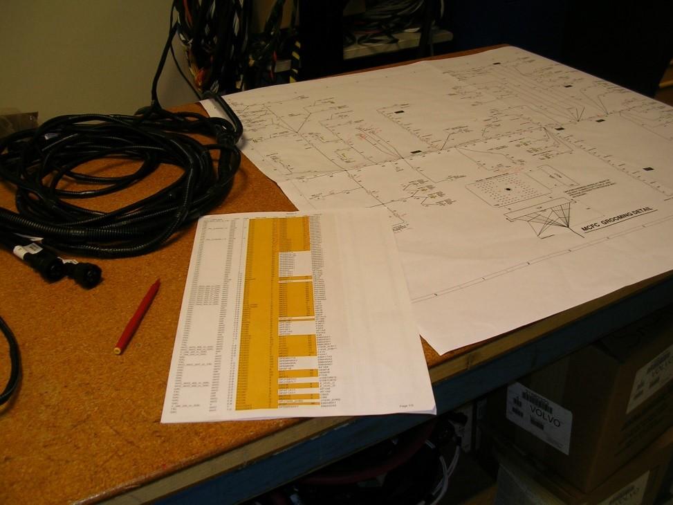
Figure 2 Manual testing of the product.
Dimensional and Structural
Dimensional and shape checks of the harness are not so difficult, these are relatively easily performed by technicians and engineers. Is this part of the harness the correct length? Is the angle of this portion of the harness 30degrees off the main trunk for example. However, continuity testing of the harness, now that can be time consuming, especially for large wire harnesses that can consist of well over 400 or more wires (making it easy to make a mistake when checking manually). Commercial vehicles are built unlike passenger cars, there are many variations and configurations of the electrical / electronic systems. As an of example, there are vehicles built where only the passenger door has a power lock and electronic window. This is but one example of the considerable diversity in the wire harness for the vehicle.
Continuity, discontinuity and cross continuity
Manually checking for continuity of a large harness bundle amounts to a spot check, as in this case only a small portion of the wire harness interconnect can be cost effectively tested via manual testing techniques before installing it on a test buck, or a test vehicle. For example, it is possible to have cross continuity, wires that should not be connected that are in fact connected. To adequately test would really require we both test the expected connections along with the unanticipated connections to the other wire elements within the wire harness bundle. Since these wire harness will end up being used in prototype vehicles, it is important to ensure these harnesses are correct, matching the design intent. From my time at one of these commercial vehicle development organizations, we learned it is better to explore the wire harness in detail to assess the veracity and conformity to the design intent before the parts are installed on these prototype vehicles. Minutes with the prototype wire harness in effective testing can save us hours and sometimes days in root cause analysis along with rework at the vehicle level.
For example, let’s assume that a prototype wire harness is built as designed, and is part of a prototype vehicle build. After the vehicle is built, we attempt to use the features of that vehicle only to find that these do not work. Why do these not work? Is it some errant software? Is it some hardware or is it the wire harness? From experience, we end up with all manner of engineer and technician climbing on the vehicle to find out what is wrong, often resulting in a partial tear down of the vehicle to get to the wire harness with a problem and make the necessary corrections. This consumes many hours and keeps the test vehicle from the track time or other testing activities this vehicle was expected to undertake. This slows down the learning along with the waste of rework. So how can we make this better? Well the wire harness prototype should be a known quantity before putting it on the vehicle, that does not mean abandoning the testing, nor performing a simple spot check on the wire harness. Now let’s look at the consequences of manually performing a point to point test of the wire harness.
Automated Testing of Harness Contacts
By way of example, let’s assume the harness has a 300 hundred connection points. A manual test might take (assume an expedient tester who averages 10 seconds per check). To test the continuity of one wire end to the other end (300 times), can be done in perhaps 10 seconds, and therefore 300 ends takes (3000 seconds) 50 minutes. However, when we test that one end for cross continuity in a harness bundle of 300 ends, we will now add time as cross continuity requires testing one wire against all of the other wires in the bundle to ensure there is not errant contact. Assuming the same time to check, each wire is tested from one end to the other end, that is 10 seconds long, now to check that end only connects to that one point, we check the other 299 ends (at 10 seconds, equals 2990 seconds or nearly 50 minutes for each wire). This will need to be done 299 more times, this is a lot of time. You may suggest, don’t perform the test. Let’s look at the consequence should we choose to do that. What happens when we build a vehicle with all of the parts surrounding the wire harness, only to find out some anomalous system performance and we have no idea the reason – the wire harness may be the culprit. The determination of the reason for the failure will take more time and will almost assuredly require tearing down the vehicle to ensure the error is not the wire harness or to make a correction to the failed harness when it is. There are other ways, for example, automation.
Figure 3 Wire harness test fixture brains.
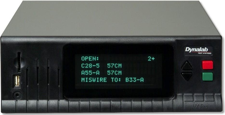
Figure 3 Wire harness test fixture brains.
A harness tester is capable of testing one hundred wires in one second and that is a much smaller time. A manual test might be 95% accurate -with some luck. The harness tester would run the test with a 99.999999% accuracy rate; the failures depend on the probably of a failure in the harness tester or in the harness test adapter cable. This test can easily perform the continuity and cross continuity testing as well as noting intermittent connection when it happens. An example of this type of fixture is the NX Pro+ fixture from Dynalab Test Systems ( I have used this systems before, I am not associated with the company) is set up to import the design documentation directly from the designer’s computer (an export of the CAD drawing) into the test fixture, minimizing documentation handling errors. The fixture has the capability of testing 32,768 test points! An adapter harness is made to connect this fixture to the wire harness device under test (DUT). A creative team might be able to find a way to connect the tester to the DUT that is quicker than an adapter harness. A configuration file is loaded into the harness tester. This configuration file is the export of the wire harness design documentation. This file contains a list of all harness test connections in the corresponding DUT (device under test or prototype) harness. This fixture then compares the harness to the design documentation in seconds. The scope of coverage is much more than what is possible through manual means and takes a fraction of the time, thus freeing up the talent of the organization to deeply explore (test) and learn about the product
Other problems are possible—the configuration file feeding the harness tester needs to be correct, that is the drawing file should be the that which the prototype part is derived. Examining the process to create the configuration file can lead to additional time savings. Creating this file by hand is not always conducive to an efficient use of time. In one case it was measured to take at least five hours to create one configuration file. We developed a simple program and we managed to reduce the execution time to about five seconds, a cost savings of at least five hours. It took two days to create the program, for a payback after about four harnesses.
Conclusion
Effective product development requires some measure of learning about the product and how the product will be used, and how the product reacts in the real world at large. Quick learning cycles are helpful for facilitating that learning. Models and prototype parts help with this learning, and therefore the schedule or time of prototype parts availability are one of the gating items for that learning. Once we have the prototype parts, we can employ automation in ways that will also help expedite and ensure the learning is valid and accurate. Both of these statements apply to all prototype work, but especially in what may seem trivial, but it is in fact not, a wire harness. It should be a fundamental principle in our work, that things we believe we know, may in fact not be precisely true, every new product development should be rife with opportunities for the team and the customer to learn, and learn quickly and to that end simulation and automation should be principle tools.